

I have an OEM amp I tore apart a while back for a random PC/Home Theater project I wanted to experiment with, but it never happened.
Anyway, here is what I did to the OEM amp today out of boredom while babysitting my kiddos.
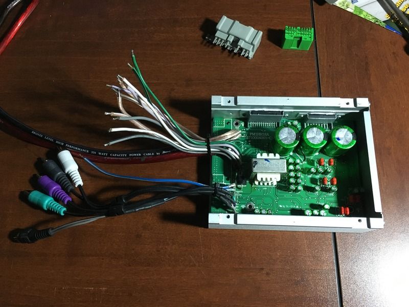
For starters I drilled new holes on the side for the ICs, dropped a thin plastic liner between the board & the chassis, and inverted the board mount so it mounts to the chassis & not the stamped steel bottom with wacky flanges.
The 4 tapped holes on the bottom of the chassis are almost exactly the same spacing as a 120mm PC fan, which could be utilized for some active cooling if necessary.
I soldered RCA cables onto the input section of the amp, color matched speaker wires on the output section, and installed 8ga power & ground cables. The 8ga wire is overkill, a 10ga or 12ga would have been perfectly fine and probably easier to work with too. Fired the amp up on the test bench & everything was working flawlessly. Had I put the chassis end caps on before soldering the power cables to the board I could have moved them over a little farther, but because the board is flipped & the plugs are on the opposite end now, the end panel has the plug holes backwards & misaligned. I may modify it to fit better, as well as fabricate an acrylic cover (with or without a fan).
Now to have a little fun with it because there are a lot of unknowns about this amp and I didnt care if I killed it so I thought Id put it through some testing & abuse.
SIGNAL RESPONSE
The front & rear channels are full range with no built in crossovers, & I did not see any integrated equalization either, which is good on both counts.
The sub channels did not have any equalization either, but it DID have an integrated low pass filter. With a full range input the subwoofer output was filtered to play everything below 800hz~1khz, which is very high for subwoofer duty but an acceptable range for a 6.5~6.75 subwoofer & less of an imaging issue because the sub is in the front of the vehicle. (this would sound awful if the sub was in the back)
POWER OUTPUT
Now for the fun part, how much juice is this thing belting out. Honda advertises it as being a 270w 7 speaker system, run by a 6 channel amplifier. Following conventional amplifier marketing (selling the peak power numbers) 270w/6ch=45w peak output / 2 = 22.5w RMS per channel (& the power rating that matters).
The actual output I measured from the front & rear channels was 18w RMS @ 4 ohm, and 33w RMS @ 2 ohm, and the output from the sub channels were measured to be 36w RMS @ 4 ohm & 66w RMS @ 2 ohm. All tests done at 13.8v & driven to the edge of clipping.
Interestingly enough the sub channels are exactly twice the output of the fronts, telling me this is an 8ch IC with stacked channels for the sub section to boost it's output.
(18x4)+(36x2)=144w RMS x2 = 288w peak output, or using the 2ohm values (33x4)+(66x2)=264w RMS.
I was pretty impressed to see the numbers on the sub channels, and they seemed to run at 2 ohm without fault. The two channels share a common input so they are a true mono output, but they are also distinct channels & cannot be bridged together. The fronts & rears ran fine at 2 ohm when testing, and the only thing I saw was the amp ran a bit hotter. I do not have the equipment to run all channels simultaneously at 2ohm, I could only test one channel at a time so there is a possibility that driving multiple channels at 2ohm could push the amp into thermal protection.
My element did not come with any of the original speakers, but has anyone confirmed what the impedance is of each OEM speaker?