Honda Element Owners Club banner
41 - 60 of 91 Posts
Well, it was time to actually make it happen - I've studied the system, tried to determine what would and wouldn't throw EVAP codes, designed and built a second tank, and have installed it. It works great!

Photo 1: where I've placed it. In the unused driveshaft tunnel. Nice safe place. Its floor is higher than the stock tank so it's not the new low spot or anything.

Photo 2: installed in the E. total capacity is now 28 gallons. Completely transparent to the end user. You simply fill through the stock filler neck, peg the gas nozzle, and they fill together. they also drain together so the fuel gauge just drops much more slowly...

Photo 3: 400 miles at half-tank... I was even towing a small trailer. Averaged 27 mpg on the 2500 mile trip. Made it on one tank of fuel from Sacramento, CA to Phoenix, AZ. When not towing, should be good for 850 miles.

Doesn't throw codes or anything. I specifically avoided moving the exhaust system and so on - so the rest of the undercarriage is still 'stock'. Very happy with the outcome.
 

Attachments

That's awesome. Too bad I have one of those pesky driveshafts in the driveshaft tunnel. :)

Looks nice though. I wonder how accurate your gas gauge is now.
 
Thanks, Island E.

Baffles: You bet. I have one every 24 inches apart. The photo below is a shot of the inside of the tank. Fuel can flow around the two small corners in the bottom. I've left a small 1/2" air gap to the roof. They also stiffen the tank by keeping the box-section from twisting.

Fuel gauge:
Part of the design was to keep the gauge pretty linear. It works well. I usually hit:

3/4 around 200 miles
1/2 around 400 miles
1/4 around 600 miles
E around 800 miles.
 

Attachments

Props on the diy tank. Looks super legit
 
Pretty slick.

Also would like to see how the lines are tied into the stock tank.
 
very nice.
 
That's quite a bit of engineering there, Watt-man. I'd be interested to see what temperature that tank might reach, being so close to the exhaust along its entire length.
Thanks everyone. It was a special project that was important to me, much like the 6-speed mod. A must!

Let's address the temps.

Agreed, I was wondering how the placement would affect the fuel system. My plan was to measure fuel temps in the stock setup, then build the tank with heat shields (three - one for the cat, one for the resonator, one for the muffler)... then monitor fuel temps "after" to hopefully prove that temp increases were nothing to worry about.

This will take three posts as I'm limited to three pictures per post.

I decided to mount the heat shield for the cat and muffler from existing shielding under the E - and mount the middle (resonator) shield from the tank itself, with minimal thermal contact by making some bosses on the lathe that I could weld to the tank. Then natural airflow under the E, in the direction of travel, should solve the problem.

It seems to have worked well. I'll show temps on the third post, but I could drive the car 10 miles, come home and raise it up on the jack, and place my hand between the cat and shield (HOT) and then simply move my hand on the other side of the shield (where the 2nd fuel tank was going to go). Cool and comfy - and so far, so good.

The first picture is the heat shield for the cat before installation, and the second picture is after installation. Essentially, the photo perspective is from "what the tank sees". Didn't want to move any components (been there, done that) so you can see the idea was to allow the O2 sensor wiring to run directly through the shield. In fact, the hole size was selected for the wiring connector to pass through and be reconnected. The third picture shows it completed, and I've labeled the cat, the shield, and the tank. You can see how the cat can't see the tank, if you will.

The rear shield for the muffler is very similar - no wiring needed to cross it. I'll get to the middle shield in the next post.
 

Attachments

Ok, now to the middle shield. this should be pretty self-explanatory - I made some bosses on the lathe, welded them to the side of the tank to hold the shield off the tank except for the three contact points, then connected the two with fiber washers in the stack. Rolled the bottom edge of the shield so it's not sharp.

Second shot shows the installation - and you can see that to leave the exhaust system completely untouched, I placed a circular cutout in the tank body to leave ample room around the factory exhaust hanger. You can see the forward and middle heat shields in this shot too. If you go back to post #41, you can see the third heat shield bolted to the Honda Heat Shield for the muffler.
 

Attachments

That is a beautiful tank...I would be interested in a tank to replace the factory one for higher clearance.:roll:
 
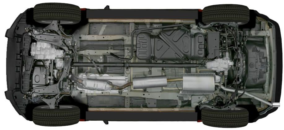
OK, so now to finally answer Ramblerdan's question about temperatures. I placed a thermocouple in the fuel line, measuring temperature of the fuel headed towards the engine. First I ran it stock. The primary source of fuel heating is the warm air coming off the radiator - slowly heating the entire fuel tank, as it is bathed in a mixture of ambient and radiator exit air.

Essentially, you'll see the fuel temps stabilize some number of degrees above the ambient air temps. In the summer this is the highest, as the air exiting the radiator is attempting to remove the most BTU/hour out of the cooling system. It takes about two hours for things to stabilize. I've tested other cars in the past and would see maximum fuel temperatures stabilize around 15 to 20 degrees above ambient in the summer. The E was no different... around 20°F hotter than the outside air temp.

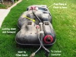
Then I completed the installation of the second fuel tank and left the instrumentation attached - then drove 550 miles non-stop, towing about 1000 pounds. The results are below. Bottom line: still only 20°F over ambient.

ANALYSIS:
The left scale in the plot below is temperature, °F. The pink line is ambient air temps, the yellow line is fuel temp. The bottom scale is time, from 11AM to about 8:15 PM. Note that the pink and yellow start at the same value and as I started the engine and drove for the first 3 hours (Phoenix to Kingman), the ambient air temp was pretty stable at just over 100°F, and the fuel temps climbed away from this value and stabilized around 20°F higher at around 120°F.

The blue line is the difference between the yellow and pink lines, and is displayed on the right scale. 20°F delta once stabilized.

Then from Kingman to Vegas, you can see the ambient temp climb from 100°F or so to 112°F or so. The fuel temps climbed too, but there's a lag in how long it takes to heat all that fuel, so the delta t appears lower (around 15°F) as ambient temps are climbing.

Then from Vegas to Ely, the opposite happened. The air temps dropped from 112°F down to around 72°F, and now the fuel temp dropped as well, but delayed due to the time constant. So the delta t along that section looks higher, around 25°F.

So - bottom line - I'm still seeing fuel temperatures similar to stock.
 

Attachments

Well, I think this is a first on the EOC that I know of. Good work Watt-man! Rambler does bring up a good point. I'd love to see more photos of the tubes connecting between the two tanks if its possible. Im impressed.
Thanks Slobadon!

I'll cover some details now, and some tomorrow. But to at least kick off the thought process: I wanted the two tank fuel levels to go up and down as a team, but didn't feel comfortable drilling a hole in the bottom of the stock plastic tank to connect them directly and make that "easy". It just seemed too dangerous. It is easy to weld fittings on the bottom of the new tank, so you can see those AN fittings in my first post. The trick was to connect an automatic siphon line through the ROOF of the stock tank. I'll explain operation later, but here is the design of the connecting line at the stock tank.

Photo 1: Here is the stock fuel tank. I've placed a yellow arrow pointing at an unused boss in the tank wall. It is right at the "full" level in the tank. When full, a stock tank has about 3 gallons of air in it, above this point.

Photo 2: I've placed an AN bulkhead fitting through the tank at this point and attached a 3/8" fuel line to it. We'll get to how it connects to the other tank later, but let's investigate what happens on the other side - INSIDE the stock tank. By the way, there are NO Baffles whatsoever in the stock tank, so I didn't want the siphon line to easily get air in it when fuel levels are low and you hit the brakes, and all the fuel rushes to the front of the stock tank. It needed a local baffle system to put it in a quiet environment. I came up with an idea of how to use some 1" tube to do that...

Which is Photo 3. This line screws on inside the tank to the bulkhead fitting. It goes to the bottom of the stock tank. You can see the mini-sump - with it's own floor - that I built so it doesn't easily lose it's prime. The height of the mini sump was selected to match the "you need to push the car now" fuel level (about .65 inches of fuel in the tank). It is around the '15.9 gallons used' point. It works great!
 

Attachments

That is a beautiful tank...I would be interested in a tank to replace the factory one for higher clearance.:roll:
Thanks, Hotbox...

Keep in mind that the stock tank is pressed firmly up against the E's frame rails, so if you make a "higher" one, all you're doing is reducing the volume of the tank by raising its floor. So agreed, you'd have to go wider into the driveshaft tunnel to compensate.

The problem is that the factory tank has a number of features built into it which you'd have to reproduce... such as a combination rollover valve / fill vent / float, the fuel pump assembly attachment ring, one-way valve in the filler line, a secondary vent line, various extensions in the outer shell to provide air volume for expansion as well as depressions in the outer shell to provide clearance for brake lines and so on. My first thought was to make a new tank, but the more I appreciated the stock tank, the design turned to leaving the stock tank almost untouched and adding a second tank.

So my recommendation for those who want to protect the stock fuel tank: just build a protective shield for it... don't try to raise it.

The photos below might be helpful to appreciate how the fuel is carried over a narrow range, height-wise. The total tank volume appears to be 20.3 gallons - that's 3 gallons of air, and 17.3 gallons of fuel, of which 15.9 - 16 are usable.

The bottom 1.3 gallons is essentially impossible for the fuel pump assembly to comfortably access. That's shown as brown in the photos below.

The next 3.5 gallons are shown as blue, and are the fuel you're using while your yellow light is on in the dash.

The next 12.5 gallons are shown in green, and are the first gallons you use after filling the tank.

Above the green is the black - this is around 3 gallons of air. The factory rollover valve / float cuts off vent flow back to the carbon cannister at this height. On older cars there was no such volume (like my 1966) so I'm assuming this is designed to 'soften' the pressure increase when fuel expands from its temperature increasing. Air is compressible, fuel is not. This most likely allows the entire fuel system to be sealed from the atmosphere over a larger temperature range. For this reason, I also included a similarly-ratioed air volume in my second tank above the fill height.

Since we're limited to 640 pixel photos, I've provided a second photo which is a closeup of the height measurements just in case that helps anyone.
 

Attachments

This has to be one of the most well-thought out mods / thread on here. Really nice work !
 
Watt-man. Excellent thread, well presented and engineered. Impressed. Now if I did that for my E I would have to have you design the location of a trucker's helper and dump valve. I, being 70 yrs young, enjoy(read - need) to stop frequently on my trips after about 3-4 hours and driving longer would tend to be uncomfortable.
 
Watt-man. Excellent thread, well presented and engineered. Impressed.
Thanks!

Now if I did that for my E I would have to have you design the location of a trucker's helper and dump valve. I, being 70 yrs young, enjoy(read - need) to stop frequently on my trips after about 3-4 hours and driving longer would tend to be uncomfortable.
Funny that you mention that. I needed an instrumentation passage to run thermocouples, pressure lines, etc inside the cabin as I like data, not guessing. But since it is unused 99% of the time, an obvious hole in the floor or firewall seemed like a poor choice. After staring for quite a while and doing lots of measuring on potential holes sites (inside and the corresponding outside location), I came up with this... in the bottom of the SC console. I haven't used it for your purpose, but when I showed it to a friend, that's the first thing he thought of...
 

Attachments

41 - 60 of 91 Posts